Free Body Diagram Pulley
That is Fnet 0. B An appropriate coordinate system for the red box.
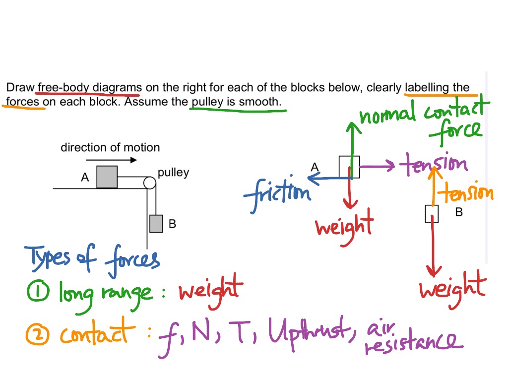
The free body diagram below shows the weight w and the tension t1 acting on the block.

Free body diagram pulley. Apply Newtons 2nd Law to write the equations for M1 and M2. The free body diagram helps you understand and solve static and dynamic problem involving forces. Free-body diagrams have been used in examples throughout this chapter.
F net 0. Draw a free body diagram for M1. On the other side of the pulley i have the force of the person holding the rope down and the tension of the rope up.
Use the free body diagram of the pulley Figure 4 to answer the Pre-Lab Questions. Free body diagram of a pulley. Draw a free body diagram for M2.
A diagram for the system of two objects and a pulley. Now replace the bracket at a in the preceding frame with another bar. Free body pulley 2 shaw3737.
Remember that a free-body diagram must only include the external forces acting on the body of interest. It is a diagram including all forces acting on a given object without the other object in the system. They plan to break the window then lower the safe 40 m to their truck.
Making accurate free body diagrams for a system of blocks connected by string and pulleys is an important step towards writing the correct equations of motio. T1 and t2 represent the tension of the string and their magnitudes are equal. A free-body diagram is a force diagram a graphic dematerialized symbolic representation that shows the relative magnitude and direction of all forces that act on an object in a specified situation.
C The free-body diagram of the red box with force components aligned with the coordinate system. Free body diagram of a pulley. T2 and fc are action and reaction pairs and therefore their magnitudes are equal.
Free-Body Diagram Example Problem 3 Bank robbers have pushed a 1000 kg safe to a second-story floor-to-ceiling window. You need to first understand all the forces acting on the object and then represent these force by arrows in the direction of the force to be drawn. Making accurate free body diagrams for a system of blocks connected by string and pulleys is an important step towards writing the correct equations of motion.
Free body diagrams The mechanical advantage of a pulley system can be analysed using free body diagrams which balance the tension force in the rope with the force of gravity on the load. Once we have drawn an accurate free-body diagram we can apply Newtons first law if the body is in equilibrium balanced forces. View The free body diagram will bedocx from PHYS ICS143 at Harvard University.
Your free body diagram should end up looking something like the figure below. M2g M1g Given M1 15kg M2 10kg Finding the torque on the pulley. Free body diagram for pulley the only two forces acting on the pulley are the two tensions.
Assume that the pulley is ideal No mass and no friction No slippage between cable and surface of cylinder ie both move with same velocity Cable is in tension but does not stretch Draw FBDs and write equations of motion. Free body diagram for each element. D and e a.
In an ideal system the massless and frictionless pulleys do not dissipate energy and allow for a change of direction of a rope that does not stretch or wear. Free-body diagrams if there is no friction. We know that this pulley system will accelerate when released so we shouldnt expect the net forces acting on the bodies in the system to be zero.
Tutorial for drawing an extended free body diagram. The free body diagram will be. Free body diagram of a pulley.
Draw a fbd of pulley b. Free body diagram of a pulley. You should get two equations with Tension in the string weight for each mass and accelerations for each mass a1 and a2.
Solution of a problem to calculate tension acceleration of a block pulley system by drawing a free body diagram the most common type of example which the students of competitive exams. The organic chemistry tutor 29819 views. Not being too clever they stack up 600 kg of furniture tie the rope between the safe and the furniture and place the rope over a pulley.
This video explains how to use free body diagram for pulley based problems. This lecture series will introduce you to the function of a pulley also called the atwood machine. A The free-body diagram of the red box.
Free body diagram for pulley the only two forces acting on the pulley are the two tensions. û ù ú h ù. The concept of a free-body diagram is widely used in engineering and physics.
